
One of the most technically important, and often misunderstood, aspects of clamp-on ultrasonic flow meter installation is transducer geometry. Different manufacturers use different terminology—sound paths, traverses, channels, direct, reflect, direct X, offset V, two and ten, three and nine, and six and twelve—but these terms generally describe the same underlying variable: the geometry of the acoustic propagation path through the pipe wall and liquid column.
From a practical installation standpoint, the large majority of clamp-on transit-time flow meter applications are resolved using one of two configurations:
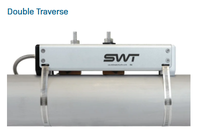
Two Traverse (Reflect)
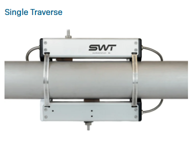
Single Traverse (Direct)
The selected traverse arrangement has a direct effect on acoustic path length, signal-to-noise ratio, transit-time sensitivity, repeatability, and the meter’s ability to maintain reliable signal acquisition under real field conditions.
Two Traverse (Reflect) Method
The two-traverse method—commonly called reflect, V-path, or two sound path—uses one transducer pair mounted on the same side of the pipe. In this configuration, the transmitted ultrasonic wave passes through the upstream transducer face, enters the pipe wall, propagates through the liquid, reflects from the opposite inside pipe wall, and returns through the liquid to the receiving transducer.
This arrangement is preferred for most clamp-on applications because it increases effective acoustic path length through the liquid while maintaining a practical installation geometry. The longer acoustic path increases sensitivity to the upstream/downstream transit-time differential used to calculate average axial flow velocity.
Technical advantages include:
Increased effective acoustic path length through the fluid
Improved transit-time resolution relative to single traverse
Better repeatability under stable hydraulic conditions
Convenient installation with both transducers on one side of the pipe
Good balance between signal strength, sensitivity, and ease of setup
In most field installations, two traverse should be the default starting point because it typically provides the best combination of measurement performance and installation efficiency.
However, two traverse depends on maintaining a sufficiently clean and coherent reflected acoustic path. If the pipe wall condition is poor, if the internal surface is heavily scaled or corroded, if the liner introduces excess attenuation or uncertainty, or if the upstream hydraulic profile is severely distorted, the reflected signal may be weakened, scattered, or unstable. Under these conditions, the instrument may experience degraded signal quality, reduced repeatability, intermittent acquisition, or complete inability to lock onto a valid measurement path.
Single Traverse (Direct) Method
When reflected-path acquisition is unreliable or not achievable, the next configuration is single traverse, also called direct mounting. In this arrangement, the transducers are mounted 180 degrees apart on opposite sides of the pipe, and the acoustic signal crosses the pipe only once without reflecting from the far wall.
Because the signal path is simpler and does not depend on a controlled internal wall reflection, single traverse is often more robust in acoustically difficult applications. This makes it a preferred fallback method for pipes with degraded wall condition, poor internal geometry, limited straight-run distance, or other conditions that interfere with reflected-path propagation.
Technical characteristics include:
Simpler acoustic propagation path
Greater tolerance to poor pipe wall condition and degraded internal surfaces
Improved robustness when reflected-path signal acquisition is unstable
Reduced acoustic path length through the fluid
Lower transit-time sensitivity and generally lower repeatability than two traverse
The performance tradeoff is fundamental: reducing the path length also reduces the differential transit-time magnitude associated with the fluid velocity vector. As a result, the measurement becomes less sensitive to small changes in flow velocity, and overall repeatability is generally reduced compared with two traverse under otherwise identical conditions. It is also more susceptible to unstable flow conditions.
In many applications, this reduction in precision is acceptable. If the measurement objective is flow verification, trending, energy balance estimation, or general process indication, single traverse may provide a more dependable real-world solution than a theoretically superior but unstable reflected path.
Why Traverse Geometry Matters
Clamp-on transit-time flow meters estimate axial flow velocity by comparing upstream and downstream acoustic transit times. The measured difference between these transit times is typically very small relative to the total absolute transit time, so measurement quality depends heavily on the acoustic path geometry and signal integrity.
Traverse geometry affects the following:
Effective acoustic path length in the fluid
Magnitude of the measured transit-time differential
Sensitivity to velocity profile distortion
Signal attenuation and reflection behavior
Susceptibility to installation-induced error
Overall repeatability and stability of the calculated flow value
Under ideal hydraulic and acoustic conditions, two traverse generally provides superior measurement sensitivity because the acoustic wave spends more effective path length in the flowing medium. However, under non-ideal conditions, a shorter and simpler direct path may provide better signal quality and more reliable signal processing, even if theoretical sensitivity is lower.
This is why installation geometry should be selected based on actual signal performance and hydraulic conditions rather than on nominal preference alone.
Practical Selection Guidance
From a technical standpoint, the preferred decision sequence is:
Start with two traverse when pipe condition, straight-run availability, and signal quality are acceptable.
Evaluate signal strength, stability, and repeatability after installation.
If reflected-path acquisition is weak, unstable, or unobtainable, consider single traverse hardware.
In field practice, if the acoustic conditions are unknown (ie, the existence and degree of scale, corrosion, particulated fluid are unknown) default to a single traverse to assure the installation will have sufficient acoustic signal.
Installation Considerations
For horizontal pipe runs, transducers should generally not be mounted at the 12 o’clock or 6 o’clock positions. The upper portion of a horizontal pipe is more susceptible to entrained air accumulation, while the lower portion is more likely to collect sediment, scale, or debris. Either condition can degrade acoustic transmission and introduce measurement instability.
Preferred mounting positions are typically on the sides of the pipe, where the liquid column is more likely to be homogeneous and free from phase separation effects.
For vertical pipes, transducer orientation is usually less restrictive, provided the pipe remains completely full and the application does not introduce significant phase separation or void fraction changes at the measurement location.
For single traverse configurations on horizontal pipes, transducer alignment should be as close as possible to true 180-degree opposition. Small circumferential misalignment can reduce signal quality and introduce additional uncertainty into the acoustic path model. In the field, a smartphone level tool can provide a practical method for improving alignment accuracy.
Surface Preparation and Acoustic Coupling
Independent of traverse selection, proper surface preparation is essential. Clamp-on ultrasonic performance depends on efficient acoustic coupling between the transducer and the external pipe wall. Surface coatings, corrosion, roughness, scale, or debris can reduce coupling efficiency, attenuate transmitted energy, and destabilize signal acquisition.
Best practice is to prepare the mounting location until the surface is reasonably smooth, clean, and mechanically consistent. Light sanding, scraping, or Scotch-Brite surface cleaning is often sufficient to improve coupling performance significantly.
Quick Technical Summary
Approximately 90% of clamp-on installations are resolved using either two traverse or single traverse geometry.
Two traverse is generally preferred because it provides greater acoustic path length and better transit-time sensitivity.
Single traverse is the preferred fallback when pipe condition or hydraulic distortion prevents stable reflected-path acquisition.
The best installation is not always the one with the longest path; it is the one that provides the most stable and repeatable acoustic signal under actual field conditions.
Avoid 12 o’clock and 6 o’clock mounting locations on horizontal pipes whenever possible.
Good surface preparation is essential for consistent acoustic coupling and reliable measurement.
Conclusion
Although the terminology surrounding clamp-on ultrasonic transducer arrangements is often inconsistent, the engineering decision is fundamentally about acoustic path geometry and signal integrity. Two traverse should generally be used when the pipe and process support a stable reflected path because it offers superior transit-time sensitivity and repeatability. When those conditions are not present, single traverse provides a simpler and more acoustically robust alternative.
Understanding the strengths and limitations of each configuration allows the installer to make a technically sound selection, improve acquisition reliability, and optimize overall measurement performance in real-world applications.
For application-specific guidance, contact SWT Engineering.
