Measurement accuracy in a transit-time ultrasonic flowmeter depends directly on the quality of the setup data and the hydraulic conditions at the installation point. Two of the most important inputs are:
Pipe outside diameter and wall thickness
Upstream straight-pipe length
1. Pipe Dimensions and Their Effect on Calculated Flow Rate
A transit-time flowmeter fundamentally measures fluid velocity along the ultrasonic path. It does not directly measure volumetric flow rate. To convert measured velocity into volumetric flow, the instrument uses the pipe geometry entered during setup to calculate the internal flow area.
The key relationship is:
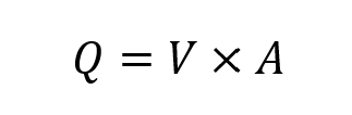
Where:
(Q) = volumetric flow rate
(V) = average fluid velocity
(A) = internal cross-sectional area of the pipe
The internal diameter is determined from the entered pipe dimensions:
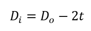
Where:
(D_i) = inside diameter
(D_o) = outside diameter
(t) = wall thickness
The internal cross-sectional area is then:
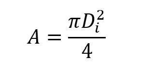
Because area is proportional to the square of the inside diameter, any error in the entered pipe dimensions propagates nonlinearly into the calculated flow rate.
Error Propagation
If the entered dimensions produce an inside diameter that is larger than the true value—for example, because wall thickness is understated—the instrument will calculate an area that is too large. Since the measured velocity is multiplied by that area, the reported volumetric flow rate will also be too high.
For small dimensional errors, the approximate relative error in area is:
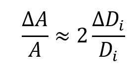
This means that a 1% error in inside diameter produces approximately a 2% error in calculated area, and therefore approximately a 2% error in volumetric flow rate, assuming the velocity measurement itself is correct.
Sensitivity Increases as Pipe Size Decreases
The effect of dimensional uncertainty becomes more severe as pipe size decreases, because a fixed absolute measurement error represents a larger percentage of the internal diameter.
For example:
A 0.01 in error on a pipe with a 1.00 in diameter corresponds to roughly a 1% diameter error, which produces about a 2% flow-rate error
The same 0.01 in error on a 10.00 in diameter pipe corresponds to roughly a 0.1% diameter error, producing only about a 0.2% flow-rate error
As a result, direct dimensional measurement is especially important on small-diameter piping, where nominal dimensions and tolerance stack-up can produce significant flow error.
2. Upstream Straight Pipe and Velocity Profile Development
The second major contributor to measurement accuracy is the condition of the velocity profile at the meter location, which is strongly influenced by the available straight-pipe run upstream.
Transit-time ultrasonic flowmeters are most accurate when the axial velocity profile is:
Fully developed
Axially stable
Approximately symmetric about the pipe centerline
These conditions improve the correlation between the velocity measured along the ultrasonic path and the true cross-sectional average velocity required for volumetric flow calculation.
Why Straight Run Matters
A transit-time meter measures fluid velocity only along the ultrasonic beam path. It does not directly sample every region of the pipe cross section. Therefore, the measurement assumes that the velocity field intersected by the beam is representative of the pipe-average velocity.
Flow disturbances caused by elbows, tees, valves, reducers, partially open control valves, pumps, or other upstream fittings can distort the velocity profile by introducing:
Swirl
Asymmetry
Secondary flow
Time-varying turbulence intensity
Under these conditions, the beam-path velocity may differ from the true area-averaged velocity, creating a systematic flow error even if the pipe dimensions are entered correctly.
Installation Implication
Increasing upstream straight-pipe length allows the disturbed profile to redevelop toward a more symmetric, fully developed state before reaching the measurement location. This generally improves repeatability and reduces profile-related bias.
As a practical minimum, use 10 to 15 pipe diameters of straight run upstream of the meter. More is generally better.
For example, on a 4 in pipe:
10D = 40 in minimum upstream straight run
15D = 60 in preferred where possible
If additional straight run is available, it should be used.
Recommended Best Practices
For applications requiring the highest achievable accuracy:
1. Measure Actual Pipe Dimensions
Do not rely solely on nominal pipe schedules or nameplate assumptions. Instead, measure:
Outside diameter using an OD tape
Wall thickness using an ultrasonic thickness gauge
These measured values should then be entered into the flowmeter configuration so that the calculated internal diameter and area reflect the actual installation.
2. Maximize Upstream Straight Run
Provide at least 10–15 diameters of straight pipe upstream of the transducers, and avoid installations immediately downstream of strong hydraulic disturbances whenever possible.
3. Treat Small Pipes with Extra Care
Because dimensional uncertainty has a proportionally larger effect on small pipes, verify dimensions carefully in small-line applications and be especially conservative about installation quality.
Conclusion
For a transit-time ultrasonic flowmeter, volumetric accuracy depends not only on the instrument’s velocity measurement performance, but also on the correctness of the entered pipe geometry and the representativeness of the local velocity profile.
In practice, two of the most effective ways to improve accuracy are:
Measure actual pipe outside diameter and wall thickness
Install the meter with adequate upstream straight-pipe run
These two steps significantly reduce avoidable setup and installation error, and they are often the difference between acceptable performance and highly accurate measurement.
If you have questions, please contact us for more information!